
1. What is the purpose of a multi speed control?
The goal of multi speed control is to be able to proceed between multiple programmed speeds thanks to logic inputs on the variable speed drive (selector or contact outputs of an automation system). The speed reference is given by the configuration value corresponding to the logical inputs; we will come back to this later.
This control and speed reference mode is different from the potentiometer one. Indeed, this one stays on programmed speeds and not on constant speed variations from 0 to 100% of the maximum frequency.
2. How does-it work?
The variable-frequency drive takes the logic inputs states and turns them into a binary code, which will be related to a programmed frequency value. This value will be registered in the settings as in percentage of the maximum value frequency.
The VSD start and stop command is not taken into account in this mode; it stays unchanged and it is still possible to do it via a terminal block, communication or on the VSD’s façade.
3. How to carry out the wiring for this control mode?
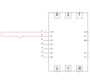
For this example, we are going to take 2 programmed speeds with a choice on a 2-position switch. This one is equipped with a NO contact (normally open); the model sold at EASI-Spare is the BPC_R2P_1NO.
The wiring is relatively easy; you just have to connect the switch contact on a logic input of the VSD. It is possible to use any input, terminals are found by DI (Digital Input), only the setting will indicate that this input will be used for the multi-speed command. In our example, we will connect this contact on the input DI1.
See the wiring diagram below:
What is the configuration to carry out?
To keep our example, the start and stop order command is made on the inverter’s façade. This doest not necessitate a specif setting because these are the factory settings of the inverter. However, for the speed reference that must be given by the multi-speed mode, and not anymore by the switch. Some settings will then need to be modified.
First of all, the parameter F0.03 must be set at 6 so that the frequency control is done by the multi-speed mode. Then, it is necessary to inform the inverter that the entry DI1 (where the switch is connected) is the multi-speed input terminal. To do so, the setting F1.00 is used for indicating what receives the input – in our case, it is the multi-speed command. It needs to be set at 12. Now that the settings for the speed reference are made, speeds need to be set. This will be made in frequency rate of the maximum rotation.
Above all, we need to set the maximum frequency that we want. It is made via the parameter F0.19 (generally 50 Hz). Thereafter, the two speeds of our example can be set from the parameter E1.00 and E1.01, by indicating a percentage value (0 to 100%) of the maximum frequency set previously (F0.19).
How to develop this system with more speeds?
To develop this controlling mode with more speeds, we need to add command contacts on DI inputs. It is possible to enhance this command up to 16 set speeds with the help of 4 contacts.
The speed selection will be made according to the inputs state in accordance with the chart below:

The typology of settings remains, we need to indicate to the inverter what receive the inputs in the parameters F1.00 to F1.03 with the value from 12 to 15 according to the number of multi-speed terminals used:

Then, we need to set the value of the percentage of the maximum frequency for each set speed. The parameters are from E1.00 to E1.15 as indicated in the second to last chart.