
| Guide to choose electrical protections |
| Here are several types of electrical protections, as well as their different characteristics. See also the wiring diagram. |
| Type of Protection |
Function | Symbol | Selection criterion | ||||
| Curve sensitivity |
Breaking capacity | Nb of poles | Nominal intensity (In) |
||||
Disconnector |
– Enables to disconnect (cut) a circuit manually. – No protection. |
 |
Nominal intensity | 1 to 4 | Choose the disconnector depending on the circuit intensity downstream. | ||
Fuse disconnector |
– Enables to disconnect (cut) a circuit manually. – Protection by fuse |
 |
Fuse activation speed: GL : AM : |
1 to 4 | Choose the fuses depending on the circuit intensity downstream. | ||
(Thermal magnetic) circuit breaker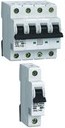 |
– Circuit disconnection downstream. – Automatic activation for protecting installations: – against overloads (overage In, see curve). – against short-circuits. See detail |
 |
Curve B: 3-5xIn Curve C: 5-10xIn Curve D: 10-20xIn Choose the circuit breaker depending on the activation speed. |
Maximum limit for short-circuit current (4.5, 6, 10… KA) | 1 to 4 | Choose the disconnector depending on the circuit intensity downstream, for overload protection | |
Residual current device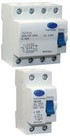 |
– Circuit disconnection downstream. – Activation in case of insulation fault. See detail |
 |
Differential sensitivity: 30 mA, 300 mA | Maximum limit for short-circuit current (4.5, 6, 10… KA) | 2 or 4 | The disconnection speed is calculated for this intensity. | |
Residual current circuit breaker |
– Circuit disconnection downstream. – Automatic activation for protecting installations: – against overloads. (overage In, see curve). – against short-circuits. – against insulation faults. See detail |
 |
Curve B: 3-5xIn Curve C: 5-10xIn Curve D: 10-20xIn Choose the circuit breaker depending on the activation speed. Differential sensitivity: 30 mA, 300 mA |
Maximum limit for short-circuit current (4.5, 6, 10… KA) | 2 or 4 | Choose the disconnector depending on the circuit intensity downstream, for overload protection. | |
Motor circuit breaker |
– Circuit disconnection downstream. – Adjustable thermal protection: in case of nominal current overage of the motor for some time (overload). – Magnetic protection: overcurrent in the motor. – Activation in case of phase unbalance. See detail |
 |
Magnetic protection: Curve D: 10-20xIn | 3 (can also be used for a single-phase motor) | Nominal intensity adjustment range (ex from 6 to 10 A) for thermal protection | ||
Thermal relay Must be mounted on a contactor |
– Adjustable thermal protection: in case of nominal current overage of the motor for some time (overload). – Magnetic protection: overcurrent in the motor. The contact must be inserted in the contactor command line. See detail |
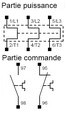 |
Magnetic protection: Curve D: 10-20xIn | 3 (can also be used for a single-phase motor) | Nominal intensity adjustment range (ex from 6 to 10 A) for thermal protection | ||